
Power Plant Water Treatment
Cleaner Condensers Higher Output Lower Costs
HydroFLOW® is power plant water treatment for the cooling circuit. It keeps condenser cooling tubes, cooling tower fill and seawater intakes clear of scale and biofouling by conditioning the water physically — a patented electronic signal induced through the pipe wall, with no antiscalant dosing and no plumbing changes. Because output is set at the cold end, clean condenser surfaces protect vacuum, heat rate and the megawatts you actually sell.
Results from named-site case studies, verified by third-party facilities managers and technical staff; outcomes vary by site conditions and baseline operation. View all power plant case studies →
Where Cooling Water Costs a Power Plant Output
In a thermal power plant, output is set at the cold end. Turbine efficiency depends on condenser vacuum, and condenser vacuum depends on clean, efficient heat transfer between the exhaust steam and the condenser cooling water. As soon as scale or biofilm coats condenser tubes, cooling tower fill or auxiliary heat exchangers, that heat transfer falls — back-pressure rises, heat rate climbs and generating output drops, whatever the fuel. And because the same water keeps flowing, the deposit returns after every clean.
Typical signs that cooling water is costing you output:
- Rising condenser back-pressure and worsening heat rate across a run
- Scale on condenser tubes, cooling tower fill and auxiliary heat exchangers
- Biofouling, mussels or barnacles restricting seawater and once-through intakes
Water in a Power Plant — and Where We Fit
Power plant water treatment is really four jobs on four different waters. Raw water is taken in and demineralised to make ultra-pure make-up; that make-up feeds the boiler and steam cycle; a separate and far larger cooling circuit carries waste heat from the condenser to a cooling tower, a river or the sea; and what is not recycled leaves as blowdown and effluent. Here is the whole map, and an honest account of which stages HydroFLOW® addresses — including the one it does not.
1 · Make-Up, Demin & RO
Raw river, borehole or seawater is screened, clarified and then demineralised through reverse osmosis and ion exchange to produce ultra-pure make-up for the steam cycle.
2 · Boiler Feedwater & Steam
Treated make-up feeds the boiler or HRSG, is raised to steam, drives the turbine and is condensed back. On a thermal power plant this is a closed loop running on demineralised water, so under normal operation it should not form scale at all.
3 · Condenser & Cooling Circuit
By far the largest water flow on site. It carries waste heat from the condenser to a cooling tower, a river or the sea. This is where vacuum, heat rate and output are won or lost.
4 · Blowdown & Effluent
Cooling tower blowdown, regeneration waste and plant effluent leave site under discharge consent, or are recovered where the plant runs towards zero liquid discharge.
The True Cost of Fouled Cooling Water
Left untreated, scale and biofouling carry a continuous cost across output, fuel, chemicals and equipment life — everywhere the cooling water flows.
Lost Output & Rising Heat Rate
Scale and biofilm insulate condenser tubes, raising back-pressure and heat rate — the plant burns more to make the same MW, or simply makes less.
Biofouling & Marine Growth
Biofilm, mussels and barnacles settle in seawater and once-through cooling lines, throttling flow and forcing shock chlorination or mechanical cleaning.
Cooling Water Chemicals
Antiscalants, dispersants and biocides mean recurring cost, chemical storage, COSHH handling risk and tighter discharge limits on cooling tower blowdown.
Cleaning Outages & Tube Damage
Scaled condensers force acid cleaning, tube brushing and unplanned deratings — each a cost, a safety concern and lost generation while units are offline.
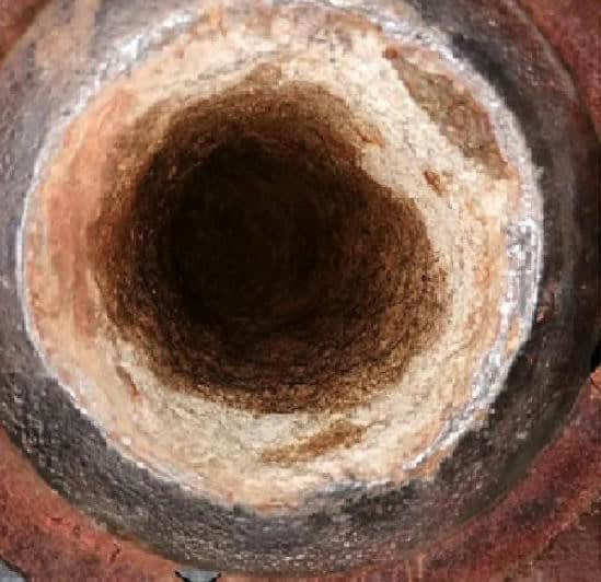
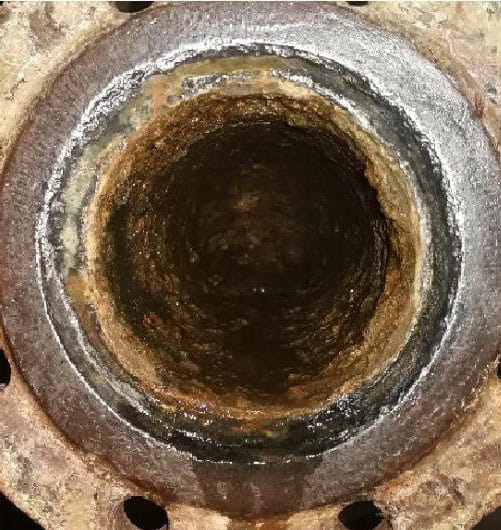
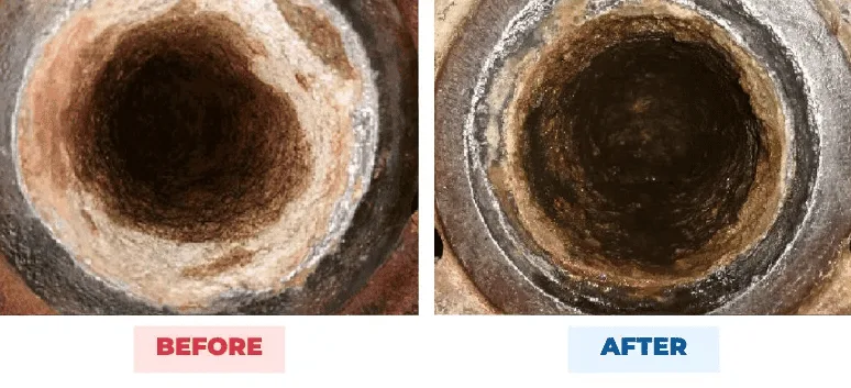
Zaporizhzhya Nuclear Power Plant, Ukraine: carbonates in hard deposits fell 63.9% and calcite up to 12 mm thick became brittle and removable, with no new deposits forming on the control beacons. Read the case study →
Where the Savings Add Up.
Scale and biofouling carry a continuous cost across the cold end of a power plant — output, fuel, chemicals, water and maintenance. Hydropath addresses six of the most significant recurring costs.
Protected Output & Heat Rate
Clean condenser tubes hold design heat transfer, so back-pressure stays low and heat rate stays where the performance test put it — a China power plant gained 1 kPa of vacuum pressure, with transit temperature falling from 5–6°C to 4–5°C.
Lower Cooling Chemical Costs
Removes the antiscalant and dispersant load, along with the storage and COSHH handling that comes with it — on the China condenser circuit, chemical dosing was stopped one week after installation.
Biofouling & Seawater Intakes
Disrupts the biofilm that mussels and barnacles need to settle in seawater and once-through circuits, cutting shock chlorination and mechanical cleaning — a China LNG plant saw bacteria fall 97% with an estimated $56k saved.
Fewer Cleaning Outages & Deratings
Less acid cleaning and tube brushing, and fewer scale-related deratings — every clean avoided is generation kept online. At Zaporizhzhya nuclear plant, calcite up to 12 mm thick became brittle and removable, with no new deposits formed.
Water Saved & Reduced Blow-down
With hardness held in suspension rather than deposited, many tower circuits run higher cycles of concentration — cutting blow-down and the make-up needed to replace it. This matters most where abstraction is licensed or the plant sits in a water-stressed catchment.
Longer Condenser & Exchanger Life
Fewer acid cleans and less under-deposit attack help protect condenser tubes, distillate coolers and auxiliary heat exchangers — deferring retubing and replacement on assets that are expensive to take out of service.
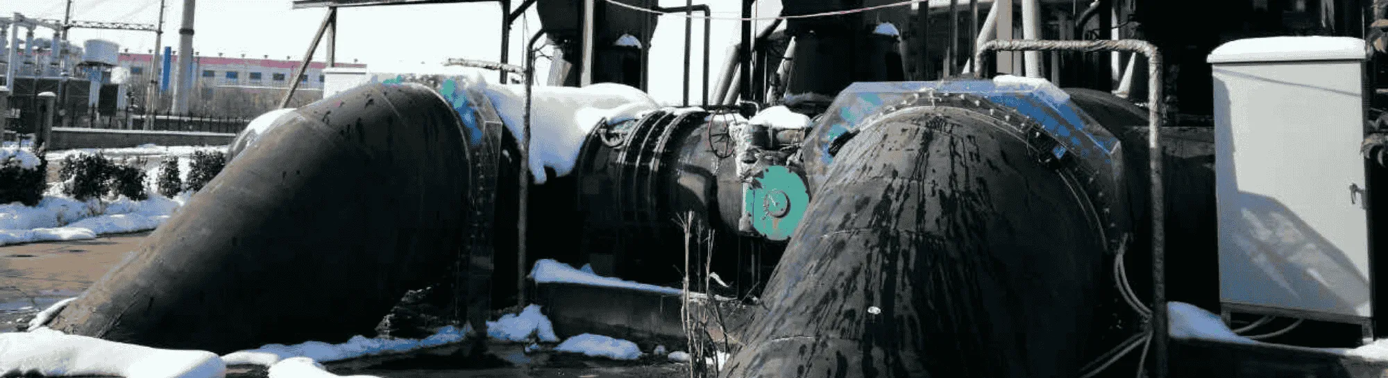
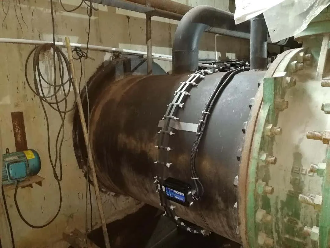
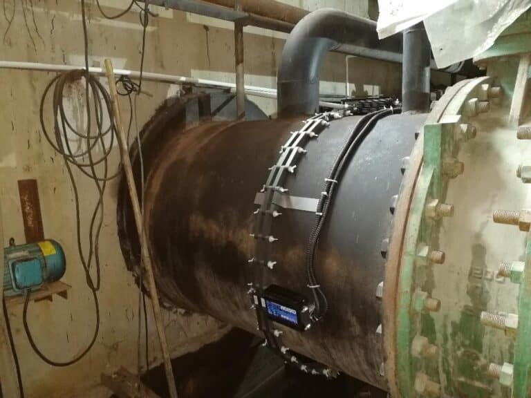
China power plant: two HydroFLOW® Multihead 72″ units on an 1,800 mm steam-condenser cooling line, fitted without a shutdown — no hard scale at the three-month inspection and chemical dosing stopped after one week.
Inland power plant in China with HydroFLOW units fitted to the steam-condenser cooling lineDon’t take our word for it — test it on your own cooling circuit.
Every figure on this page is designed to be independently verified using a documented, step-by-step testing protocol run on your own condenser cooling water, cooling tower or seawater circuit.
Get a Free Cooling Water Assessment
How We Keep Condenser Tubes Clean and Lower Chemical Dosing
A physical conditioner for condenser cooling water, cooling towers and seawater intakes, powered by a patented electronic signal
HydroFLOW® induces a patented ~150 kHz signal into the cooling water through the pipe wall. The signal changes how dissolved minerals behave: instead of bonding to condenser tubes, cooling tower fill and heat exchangers as hard calcium carbonate scale, calcium and magnesium ions form loose clusters in the water. When the water becomes supersaturated, those clusters crystallise in suspension — as fine crystals carried harmlessly through the circuit rather than cemented to heat-transfer surfaces.
The result is scale control at the point where deposits are born — the moment of crystallisation — with no antiscalant or acid dosing and no plumbing changes. The same signal disrupts the conditions biofilm and shellfish need to settle, so biofouling is controlled alongside scale on recirculating, once-through and seawater circuits alike. The signal propagates in both directions through the pipework, so a small number of correctly sized installation points protect the whole cooling circuit, working continuously, 24/7 — while the plant stays in service.
Learn More About Our TechnologyApplications
Key applications for power plants
Cooling water touches almost every corner of a generating plant. Each application links to its dedicated treatment page.
Condensers & Heat Exchangers
Reduces fouling on surface condensers, distillate coolers and auxiliary plate and shell-and-tube exchangers — protecting approach temperatures and condenser vacuum.
Seawater Cooling Systems
Protects seawater intakes, screens, culverts and once-through cooling lines from marine growth and scale — the same physics used across marine, offshore and LNG cooling.
Biofouling & Biofilm
Helps control the biofilm that lets mussels, barnacles and marine growth settle in seawater and once-through circuits — reducing shock dosing and mechanical cleaning.
Cooling Towers
Controls scale on fill, condensers and pipework so power plant cooling towers run higher cycles of concentration with less blowdown and lower chemical dosing.
Boilers & Steam
On a thermal power plant the steam loop runs on demineralised water and should not scale, so HydroFLOW® is not applied there. Where it helps the hot end is upstream, on the RO and demineralisation trains that make the feedwater.
Reverse Osmosis & Demin
Cuts antiscalant dosing and membrane fouling on the RO and demineralisation trains that produce make-up and boiler feedwater for the steam cycle.
Process Overview
Simple Installation. No Interruption to Cooling.
Our patented technology retrofits into your existing cooling plant while the facility stays live.
The Fit
The HydroFLOW® units install around your existing condenser, cooling tower or seawater pipework — no cutting, no welding, no derating the unit. At a China power plant, two units went onto an 1,800 mm cooling line with no shutdown.
The Signal
A patented ~150 kHz signal propagates in both directions through the water, treating the circuit from each installation point — working continuously, 24/7, on recirculating and once-through systems alike.
The Results
New scale stops forming, existing deposits gradually soften and clear, and biofouling is disrupted. As condenser surfaces come clean, vacuum, heat rate, blowdown and chemical use all improve.
Proven On Site
Real Power Plants. Real Results.
Named sites across thermal, LNG and nuclear generation — all results verified by third-party facilities managers and technical staff.
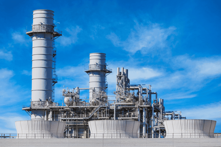
Great Lakes Plant: 200M Gallons and $350K Saved a Year
A 700MW Great Lakes power plant cut scale and corrosion inhibitor use by 75.5% and saved 200 million gallons a year across its 10-cell cooling tower.
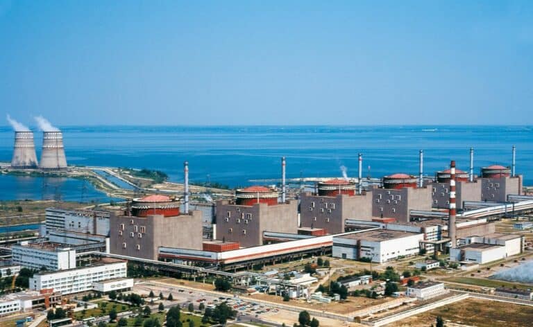
Ukraine Nuclear Plant: Hard Scale Softened, Biofouling Gone
Two HydroFLOW Industrial test units softened hard carbonate scale and removed biofouling at a Ukrainian nuclear plant.
China LNG Plant: 97% Less Bacteria, $56k Saved
Two HydroFLOW Multihead 50" units cut bacteria 97% and improved condenser performance at an LNG power plant in China.
Support & FAQ
Frequently Asked Questions
Why does scale on condenser tubes cost a plant output?
Turbine output is set at the cold end. Condenser vacuum depends on clean heat transfer between the exhaust steam and the condenser cooling water, so as soon as scale or biofilm coats the tubes it acts as insulation: back-pressure rises, heat rate climbs and generating output falls. Because roughly 1 mm of scale can cut heat-transfer efficiency by around 7%, even a thin deposit is measurable in megawatts. Controlling scale and biofouling in that cooling water is what condenser water treatment does, and it is the part of the job HydroFLOW® addresses.
At an inland power plant in China running on Yuen River water, fitting HydroFLOW® to the 1,800 mm steam-condenser cooling line raised vacuum pressure by 1 kPa and dropped transit temperature from 5–6°C to 4–5°C, with no hard scale found at the three-month inspection.
Can you treat condenser cooling water without chemicals?
Yes, for the scaling and biofouling load — though how much dosing comes off depends on the water and the circuit. HydroFLOW® clamps around the outside of the cooling-water pipe and induces a patented ~150 kHz electronic signal into the water. The signal makes dissolved calcium and magnesium crystallise in suspension, carried harmlessly through the circuit, rather than bonding to condenser tubes and cooling tower fill as hard scale. Nothing is added to the water and no plumbing changes are needed. Some sites stop antiscalant dosing entirely: at a China power plant, dosing on the steam-condenser circuit stopped one week after installation, and at Imperial Oil's Kearl Lake facility in Canada antiscalant went from 2.0 ppm to 0.0 ppm over a twelve-month monitored trial. Others reduce it rather than remove it — a Texas factory cut total chemical use by 75%. Corrosion inhibition, pH control and any statutory disinfection chemistry are separate duties and should be maintained as your water treatment regime requires.
How do you prevent biofouling in a seawater cooling circuit?
Biofouling in a seawater circuit starts with a biofilm that lets mussels, barnacles and other marine growth settle on the wetted surfaces of intakes, screens, condenser tubes and pipework. Conventional control means shock chlorination or mechanical cleaning. HydroFLOW®'s electronic signal disrupts the conditions that biofilm and shellfish need to attach and grow, so it works alongside scale control on the same circuit and from the same installation points. The clearest evidence is a side-by-side trial at a desalination plant in Chile: one seawater suction line was treated and a second left untreated as a control, and across 223 days and four inspections the treated line held zero mussels and needed no cleaning and no chemicals, while the control line grew mussels over 3 cm. At an LNG plant in China, bacteria in the seawater cooling circuit fell by 97% with an estimated $56k saved. Biofouling control should always be verified against your site's own monitoring and any statutory requirements.
What are the additional challenges of once-through and seawater cooling?
Most cooling water chemistry is designed for a recirculating tower, where dosing is added to a fixed inventory of water. A once-through or seawater circuit has no inventory to dose — the water passes through the condenser once and returns to the sea or river — so chemical programmes are expensive, environmentally constrained and often limited to intermittent shock treatment. Because HydroFLOW® conditions the water physically as it passes through the field, it does not depend on residence time or on holding a chemical residual, which suits it to once-through, seawater and river-water cooling as well as to cooling tower circuits. In a controlled trial at a desalination plant in Chile, a treated seawater suction line ran 223 days with no cleaning and no chemicals and no mussels, while the untreated control line fouled. See sea water cooling systems for the detail.
Of the chemicals normally used in power plant water treatment, which can be removed?
A typical power plant cooling programme runs four chemistries: antiscalants and dispersants to hold hardness in solution, acid for pH control, corrosion inhibitors to protect the metallurgy, and oxidising or non-oxidising biocides for microbiological control. HydroFLOW® acts on the first and, where biofilm is the driver, on part of the fourth — and how much comes off depends on the site.
On the scale side, some circuits stop antiscalant dosing altogether — at a China power plant, dosing on the steam-condenser circuit stopped one week after installation, and at Imperial Oil’s Kearl Lake facility in Canada antiscalant went from 2.0 ppm to 0.0 ppm across a 200,000 m³/day heat exchanger system over a twelve-month monitored trial. Others reduce rather than remove: a Texas factory cut total chemical use by 75% across its cooling and washer systems.
On the biofouling side, the same signal disrupts the conditions biofilm needs to establish, which for most sites means less shock chlorination and lower routine biocide dosing rather than none — at a China LNG plant, bacteria in the seawater cooling circuit fell 97%, with an estimated $56k saved.
It does not replace corrosion inhibition, pH control, or any disinfection chemistry you are required to maintain by regulation — those stay. What changes is the scale-related share of your chemical spend, and part of the biocide load where biofilm is the problem, along with the storage, handling and discharge that comes with it.
How is HydroFLOW® used at the different stages of a thermal power plant?
Water moves through four stages in a thermal power plant. Raw water is taken in and pre-treated, then demineralised — usually through reverse osmosis and ion exchange — to make ultra-pure make-up. That make-up feeds the boiler and steam cycle, where it is turned to steam, drives the turbine and is condensed back. A separate and far larger cooling circuit carries waste heat from the condenser to a cooling tower, a river or the sea. What is not recycled leaves as cooling tower blowdown and plant effluent.
HydroFLOW® is used on the cooling circuit, which is the main application, and on the reverse osmosis and demineralisation trains that produce the plant’s make-up. It is not used on the boiler and steam loop itself: that water is demineralised and should not form scale under normal operation. HydroFLOW® does not remove dissolved solids and is no substitute for demineralisation or effluent treatment.
Can it be fitted to a nuclear or LNG plant cooling circuit?
Yes. At Zaporizhzhya Nuclear Power Plant in Ukraine, two HydroFLOW® Industrial units were fitted to 108 mm cooling water supply pipes upstream of the distillate coolers — balance-of-plant cooling duty, not safety-related systems. Between December 2019 and March 2020 the carbonate content of hard deposits fell by 63.9%, hard calcite up to 12 mm thick became brittle and removable, biological fouling was cleared during the trial, and no new deposits formed on the control beacons. At an LNG plant in China, bacteria in the seawater cooling circuit fell by 97%. Results at both sites were verified by third-party facilities managers and technical staff. Anything serving safety-related cooling would need to go through your own site qualification and regulatory approval first.
Can units be installed while the plant stays in service?
Yes. HydroFLOW® fits on the outside of the pipe, so there is no cutting into the line, no welding and no need to drain or derate the unit. At a China power plant, two Multihead 72-inch units were fitted to an 1,800 mm steam-condenser cooling line with no shutdown, and at Imperial Oil's Kearl Lake facility in Canada three Custom 24-inch units went onto heat exchanger inlet pipes on a system flowing around 200,000 m³/day. It suits steel, concrete-lined and plastic pipework, and because the signal propagates in both directions along the water, a small number of correctly sized installation points can protect the whole circuit.
Ready to Protect Output and Cut Cooling Costs?
Tell us about your plant, your cooling type and your current chemical and cleaning routine, and our team will recommend the right units and estimate what you could recover in condenser efficiency, chemicals and cleaning outages.
Ready to explore sustainable water treatment?
Get in touch to find out how HydroFLOW® can work for you.

© 2026 Hydropath Technology Ltd. All rights reserved